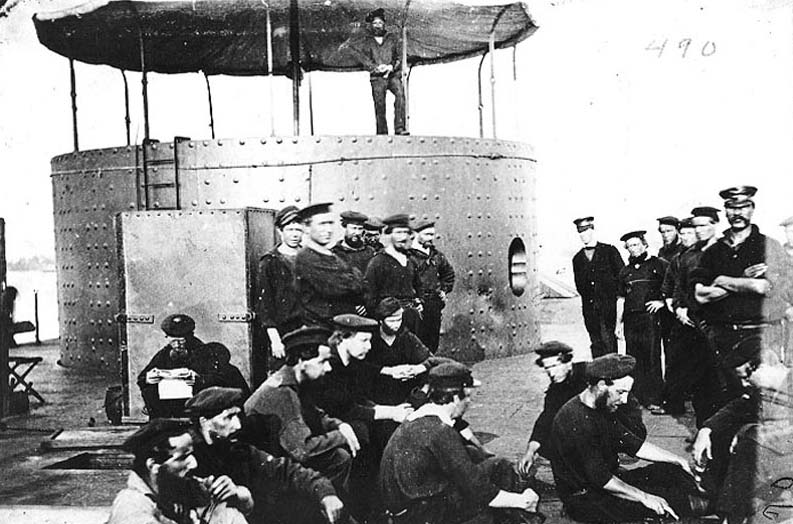
In preparation for their removal from the turret, photographic documentation was undertaken to record the location and orientation of remaining roof stanchions (in situ in their mounting brackets), which once supported a canvas canopy above the turret. In the photograph below taken in July of 1862, you can see the starboard side of the turret in the background with the roof stanchions and canopy clearly visible. (notice the dents near the gun port!!)
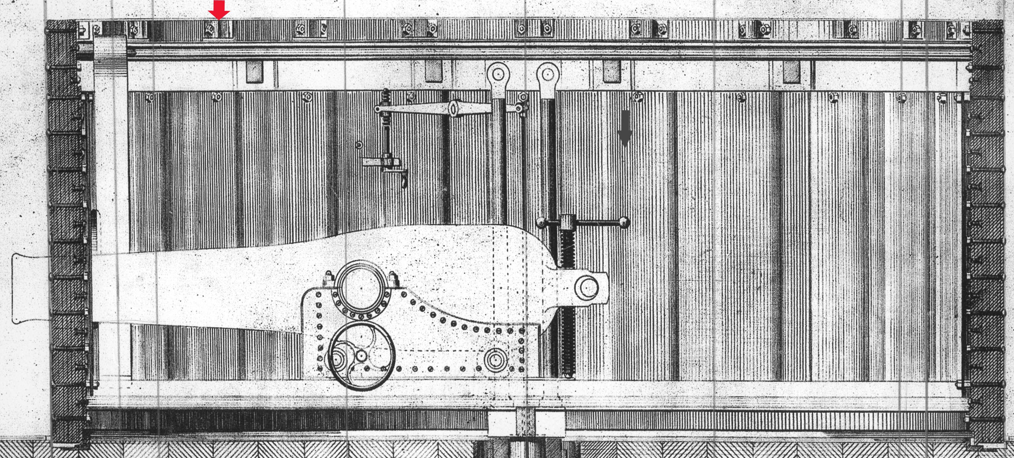
The image below is a print of Monitor‘s turret in a transverse cutaway view of the starboard side, which shows a portion of the stanchion brackets along the top of the turret above the roof.
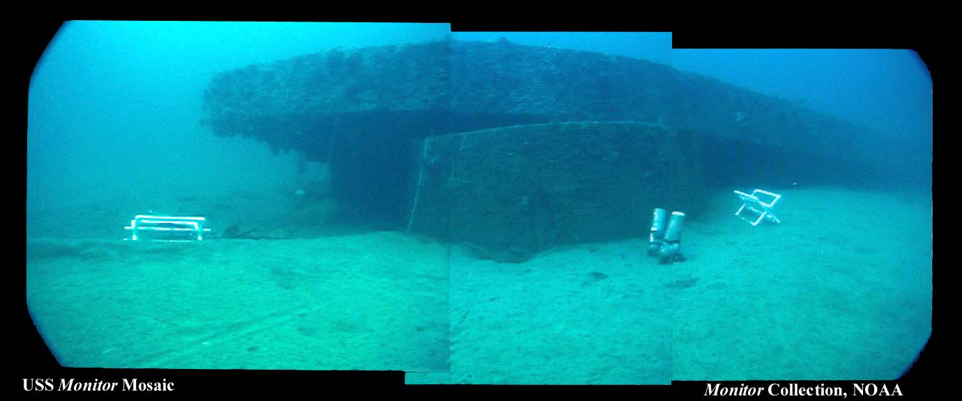
During the sinking in December of 1862, the ship rolled over and the iconic gun turret became separated from the hull and settled on the seafloor in an inverted position with the rest of the ship then landing onto of it. As one can imagine, the nature of the sinking led to the bending, distorting, and breaking of the roof stanchions that remained in place when the turret hit the ocean bottom. In the NOAA image below one can see the turret pined under the hull of the ship.
The following image taken last week shows the port-aft section of the turret in its tank within the Batten Conservation Complex (remember it’s still in an inverted position!!). You can clearly see the degree of deformation which occurred to the stanchions from the sinking as well as some material loss from more then 140 years spent on the seafloor.
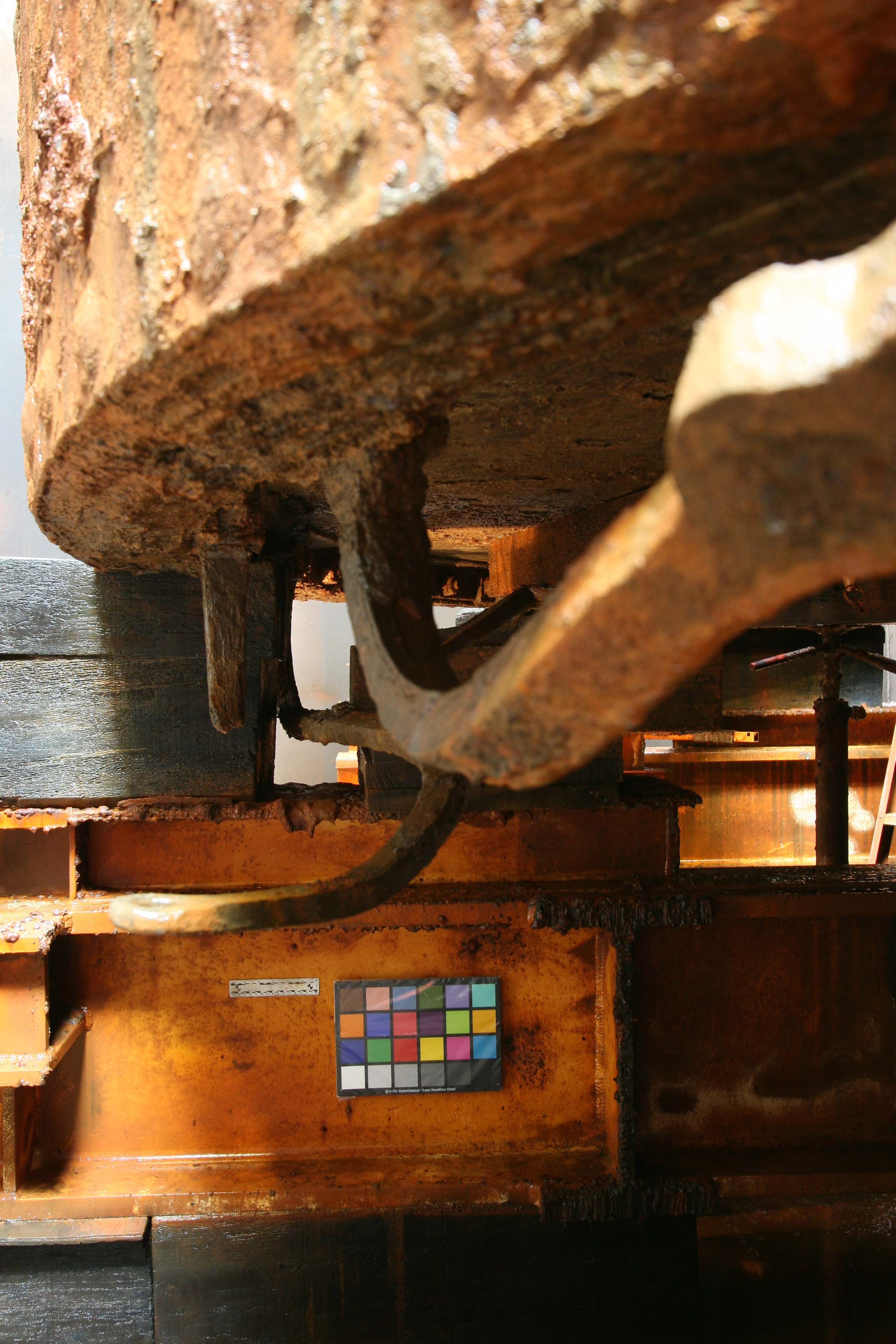
So, at this point you may be asking yourself, “Will, why is it important that you document all the remaining stanchions in position on the turret?” Well, I’m glad you asked that question. The reason it’s important is because identifying the way the stanchions are bent will aid in creating a more complete understanding of how exactly the turret landed on the ocean floor. This information could provide valuable clues which could add to the greater archaeological picture of Monitor’s final hour. The following images are some detail shots of the port side of the turret with various views. Enjoy!!!!!
The above image shows the same port-aft side of the turret as previously seen but now from an exterior view while the image below provides a composite view from the top of the turret of the same section.
The next image is a detail shot from an interior view of the stanchion and bracket to the right in the above photo mosaic.
This last image is of the starboard-aft side of the turret and I’ve flipped the image over so you are now viewing the “revolving marvel” right side up!
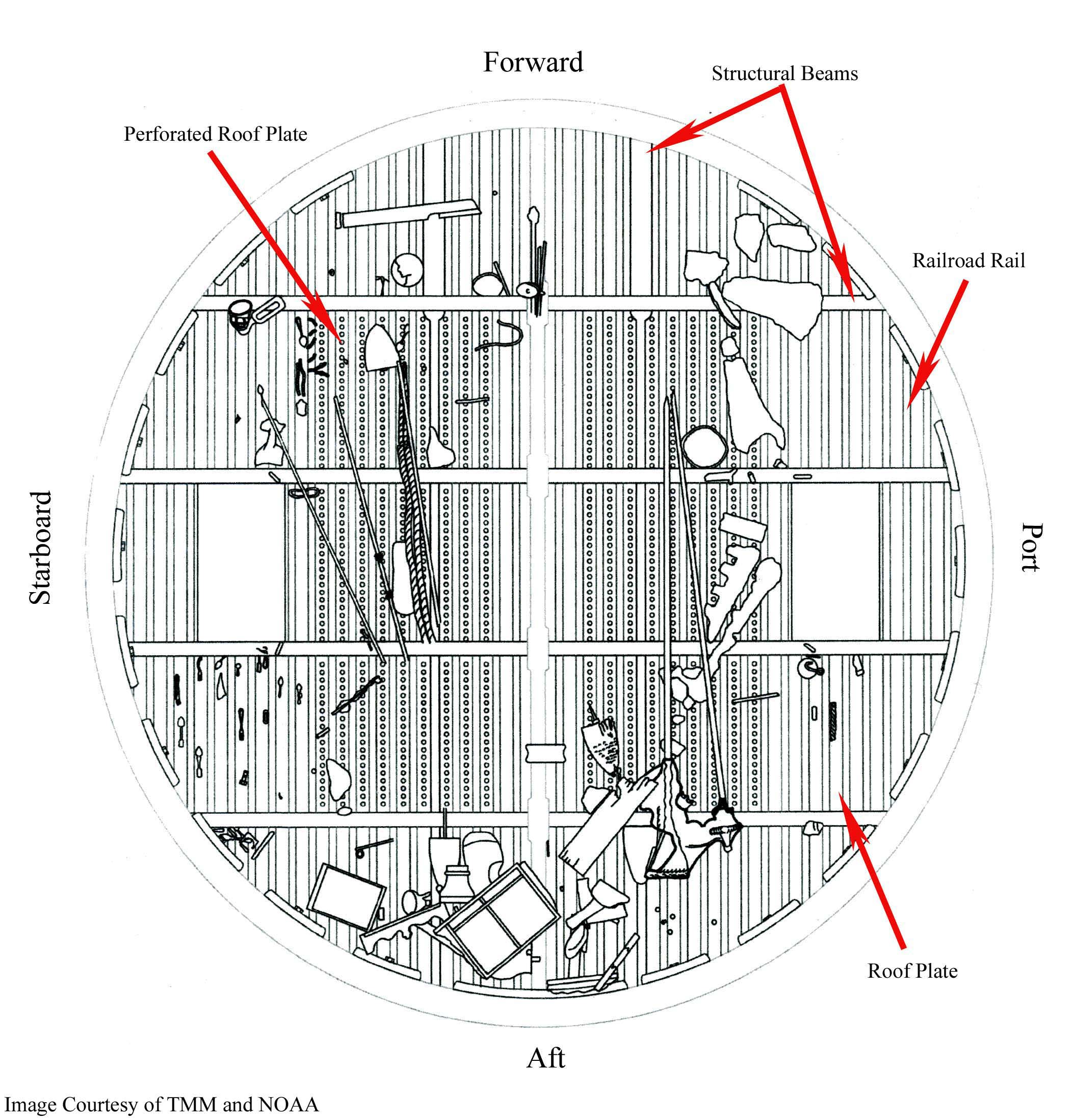
There have been some questions asked about the roof of the turret since posting, so I’ve added the image below, which is an interior view of the turret created by NOAA archaeologists showing main structural beams, railroad rails, and roof plates. Note: the drawing was created during the excavation of the turret and only a portion of the objects recovered are present in this representation.
In response to some recent questions about the turret roof and stanchions I’ve added a little more detail below:
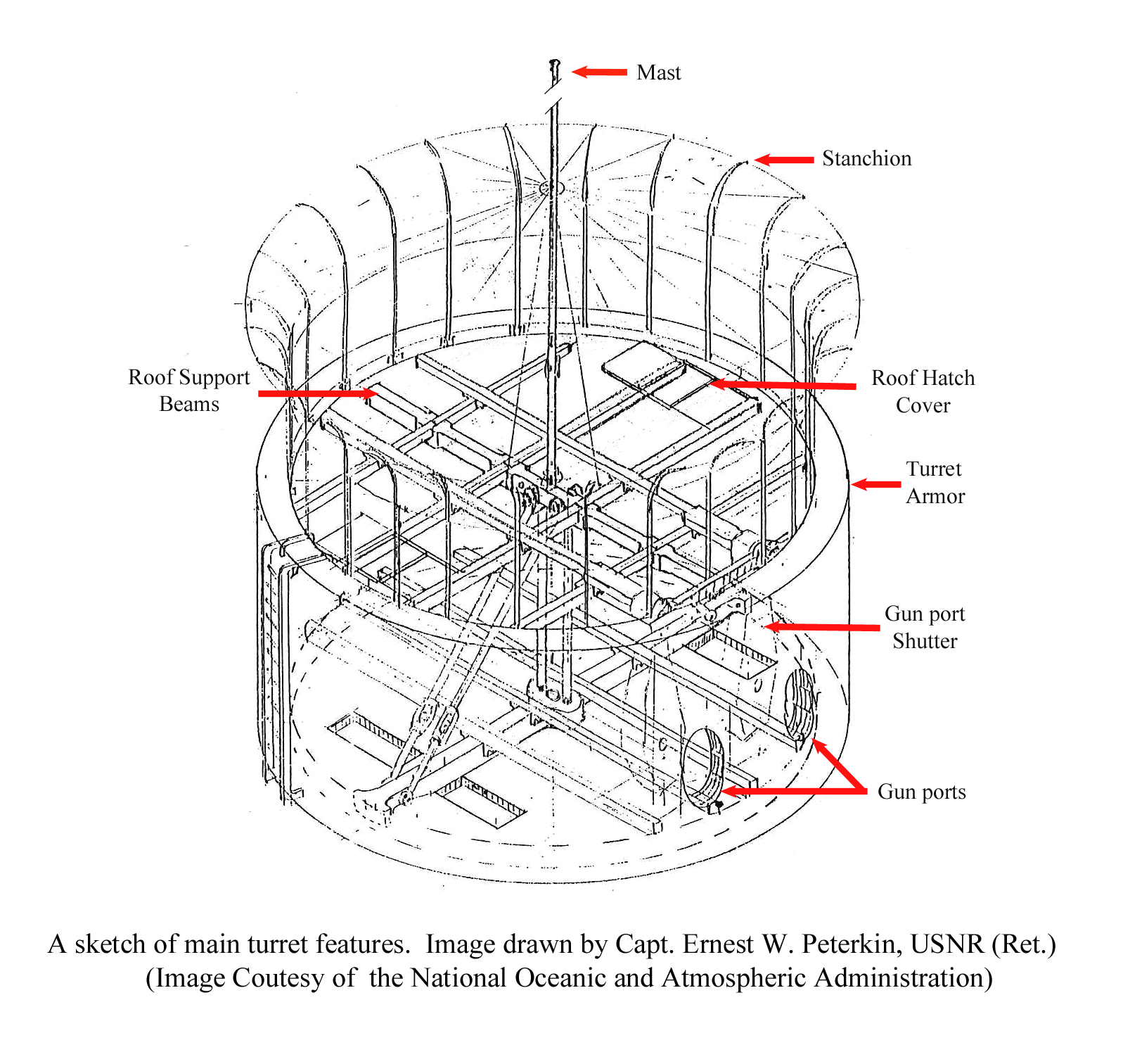
To help protect Monitor’s crew from the elements, its gun turret was crowned with a large cone-shaped canopy. The center of the canopy was supported by a mast while curved wrought iron stanchions were used to hold up the outer edge. The mast was attached to the turret’s roof by a large copper alloy socket whereas the stanchions were held by 24 brackets bolted around the inside of the armor wall above the roof as seen below and in the previous images above.
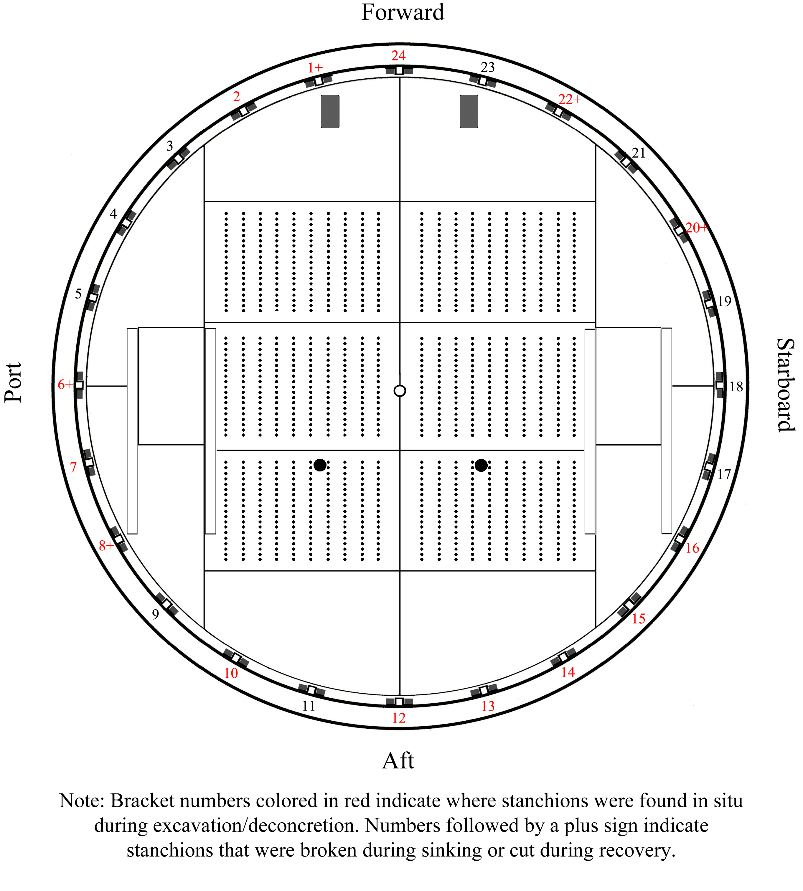
The next image shows a bird’s eye view of the turret with the approximate positions of stanchion brackets (subsequently numbered by The Mariners’ Museum) as well as other features that compose the roof, including fourteen ½-inch thick wrought iron plates. The central six plates are each perforated with ten parallel rows of nineteen holes. Also visible in the graphic are the port and starboard hatch cover rails, which extend along each side of the hatches toward the aft of the turret. The two rectangular shapes visible at the forward part of the turret are the top surfaces of the gun port shutters. The hollow circle in the center of the turret represents the mast socket. The two black holes aft of the mast socket represent openings through the roof, which may have been intended to be part of an exhaust system for Monitor’s guns as mentioned in a period document titled, “Monitor” Oct. 1861: Specification of an Impregnable Floating Battery, composed of iron and wood, complete ready for service expecting guns, ammunition, and stores.
During recovery and excavation of the turret beginning in 2002, a total of 14 stanchions (both complete and fragmented) were found in place on the the turret’s roof. This represents two more stanchions than seen in photographs taking of the ship during its time of active service. Furthmore, the positions of the stanchions are not alternatley spaced around the turret as seen in the Gibson photographs, but rather in groups with the largest grouping near the starborad – aft section in which five consecutively placed stanchions are visible (see figures 4 and 9). Interestingly, the intact stanchions are all dramatically bent in the direction of the port side, which adds to the belief that the turret landed on ocean floor with is starboard edge strking the seabed first, and then fell to port.