Last week got off to a great start as we drained the condenser tank for the first time in two years. This was the second draining of a tank since I arrived at The Mariners’ Museum and I was looking forward to getting back into one of the “big” tanks.
After draining, rinsing, and disassembling the anode rig, it was time for during treatment photographs and a brief condition assessment. The time in electrolysis has been good for the condenser; all of the iron surfaces are black with no active corrosion in sight. Taking the during treatment photos was a bit tricky seeing as we were maneuvering around inside of a steel tank that still had four inches of water in the bottom and a trench along one side. First rule of using electronics in the tank: whatever you do, don’t drop the equipment. The pictures turned out really well, as you can see in the images below. Keep in mind that the entire assemblage in upside down.

The starboard side of the condenser
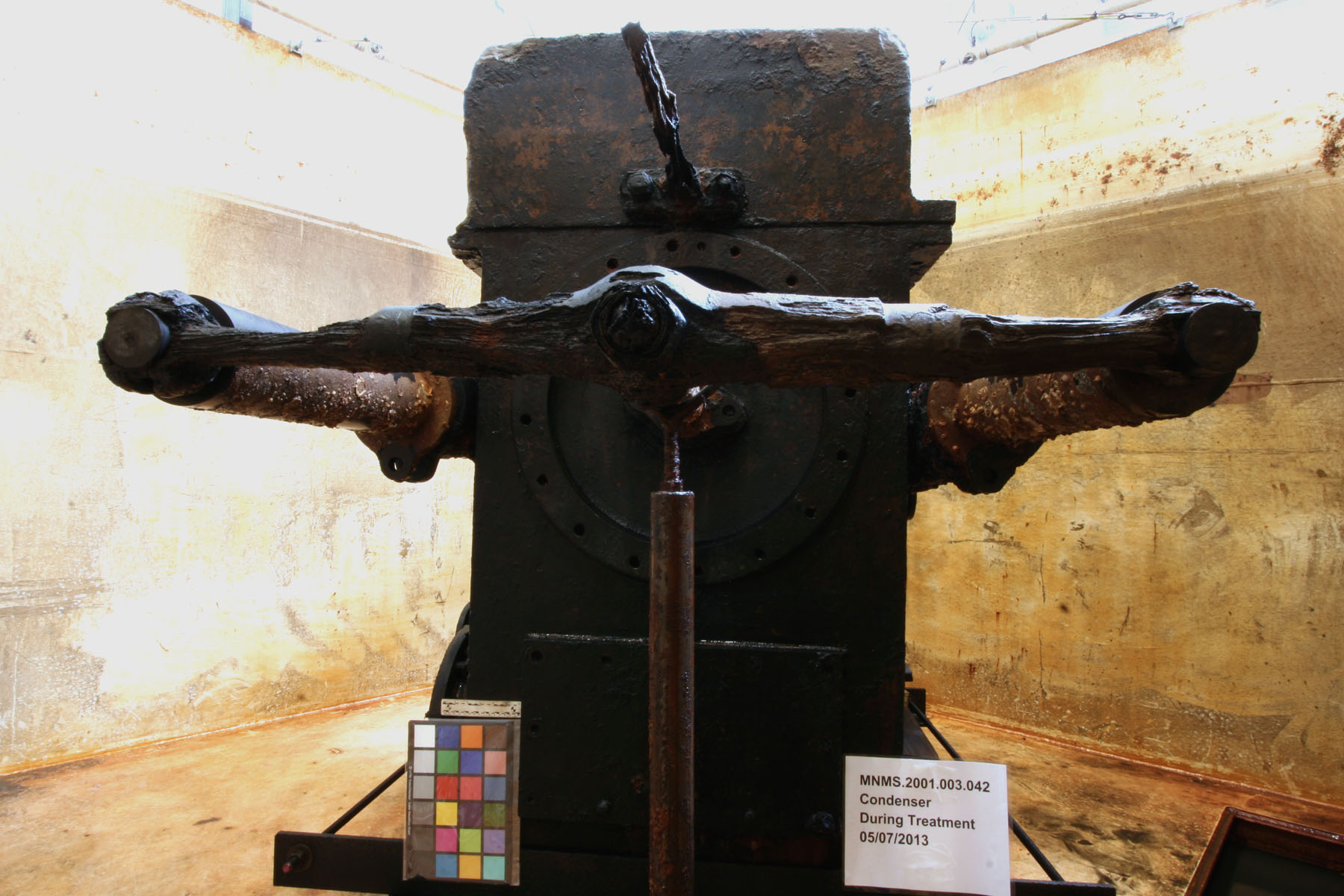
The port side of the condenser
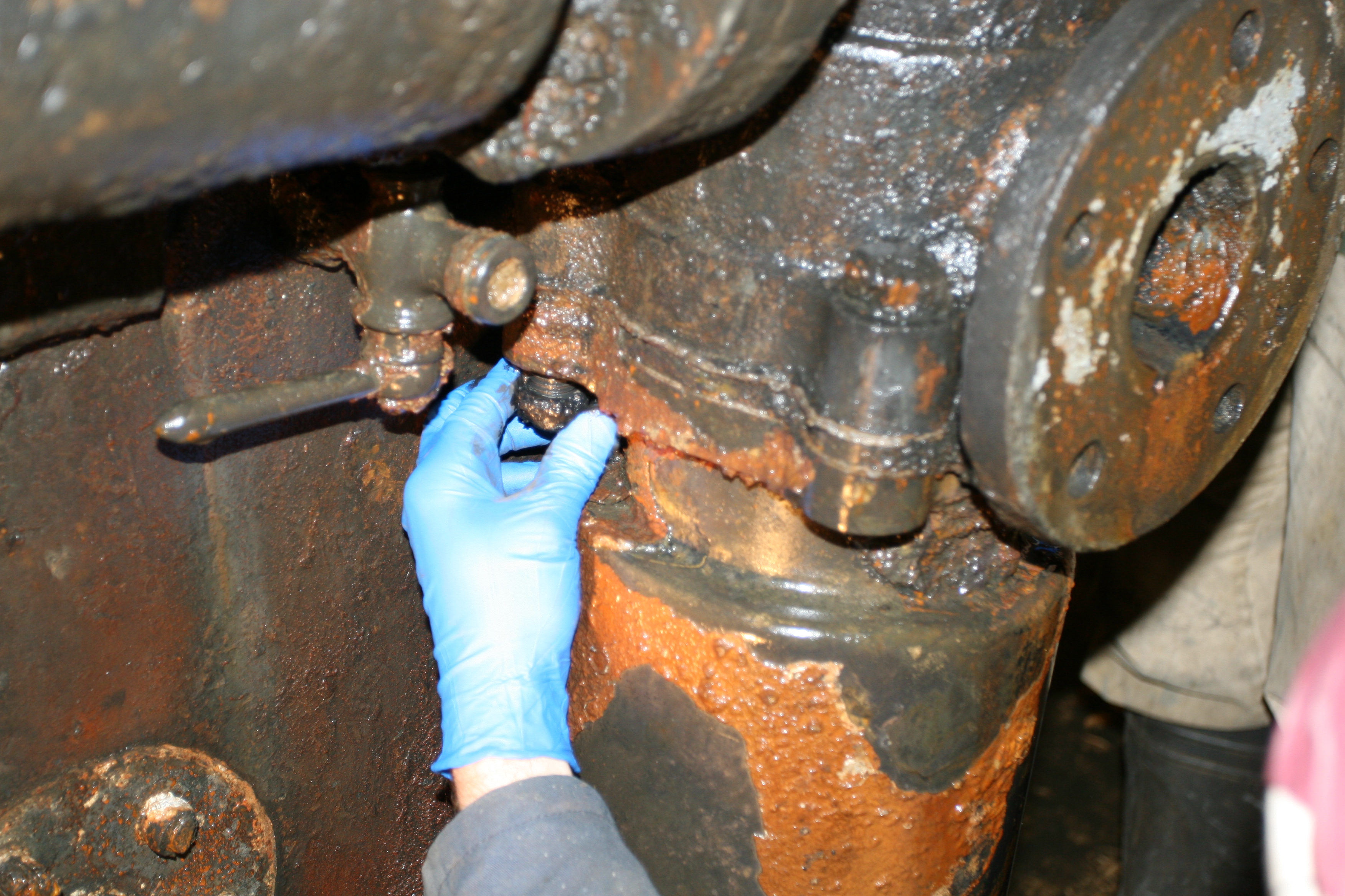
The last time the condenser tank was drained, the seawater discharge pipe was removed, but due to time constraints the conservators did not have the opportunity to clean out the valve chambers. So, armed with a hose apiece and wearing gloves that came up to our shoulders, Will and I undertook this next step in the care and treatment of the condenser. The sheer amount of muck, sediment, shells and sea urchin spines inside those chambers was impressive, but the effort was well worth it. The pictures we got from our RIDGID SeeSnake fiberoptic camera showed interior valves that were visible for the first time in 150 years.

The red arrows indicate where we were reaching into to remove sediment.
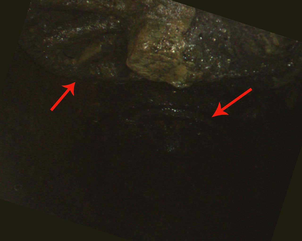
Hard to see, but the red arrows point to the interior valves.
During our condition assessment, it was noted that the copper-alloy air flask on the feed pump was starting to separate from the pump and was not held in place by as much surface area as we would have liked. It was decided that the best option would be to remove the air flask. One nut and bolt still held the flanges of the pump and air flask together, and it took only a half-turn with a wrench before the nut could be unscrewed by hand. The threads on the bolt looked like they were made yesterday. The air flask needed only a little wiggling before easily coming away from the pump.
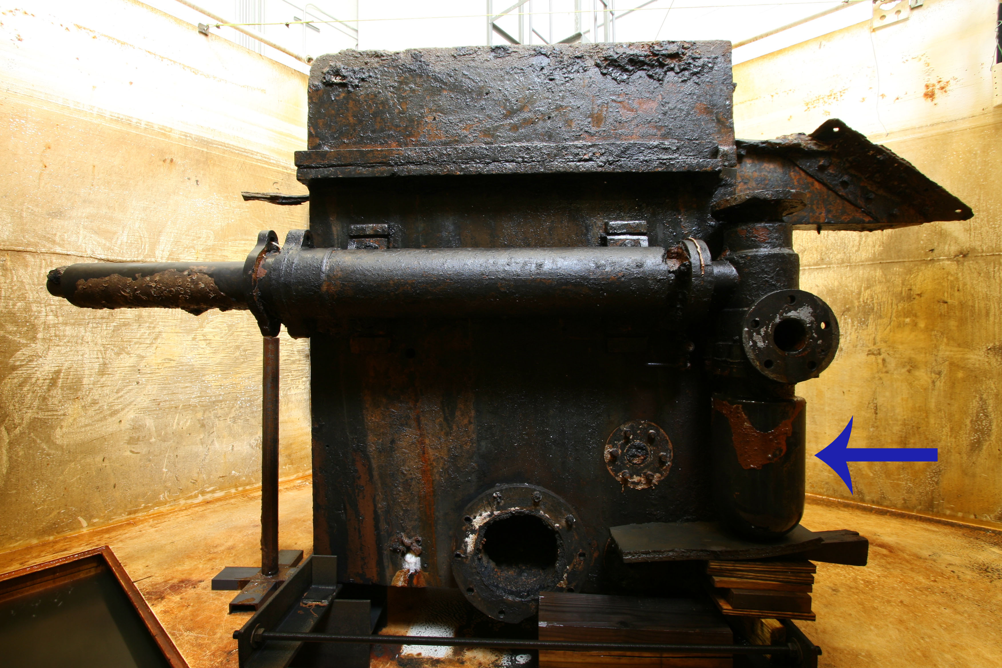
The blue arrow points to the air flask that was removed.
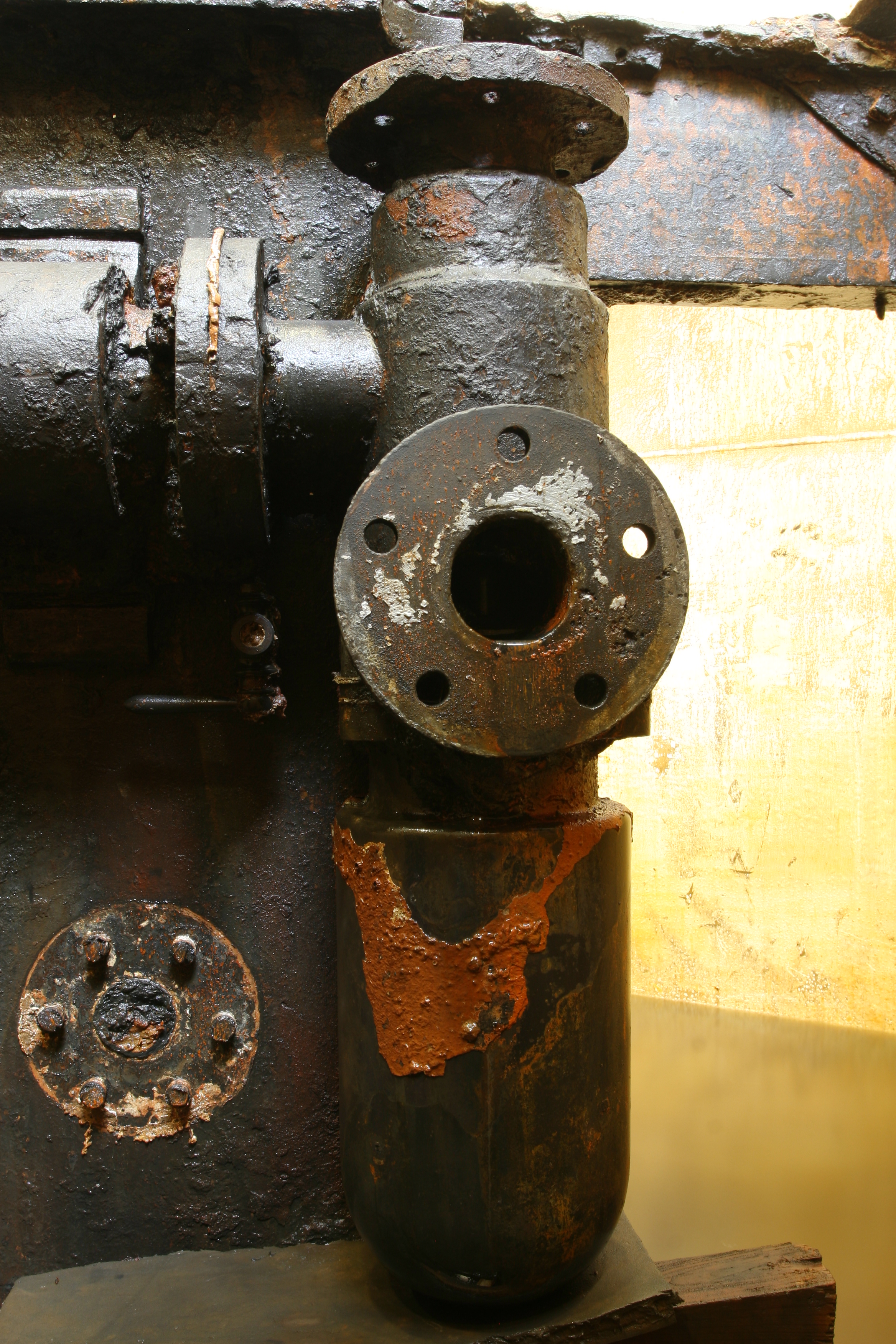
A close up of the air flask prior to removal.

Will loosening a nut by hand.
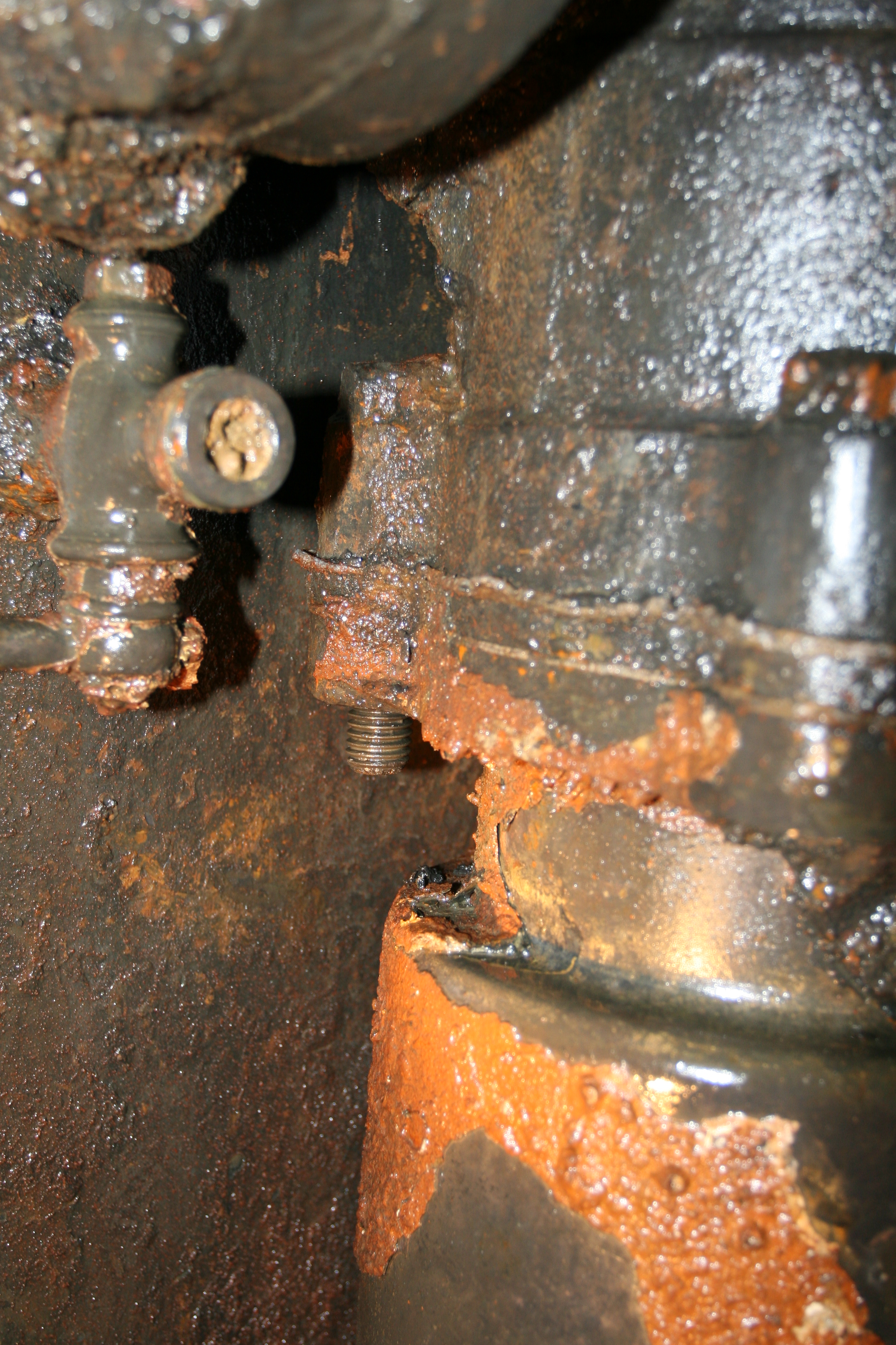
Bare threads that could have been made yesterday.
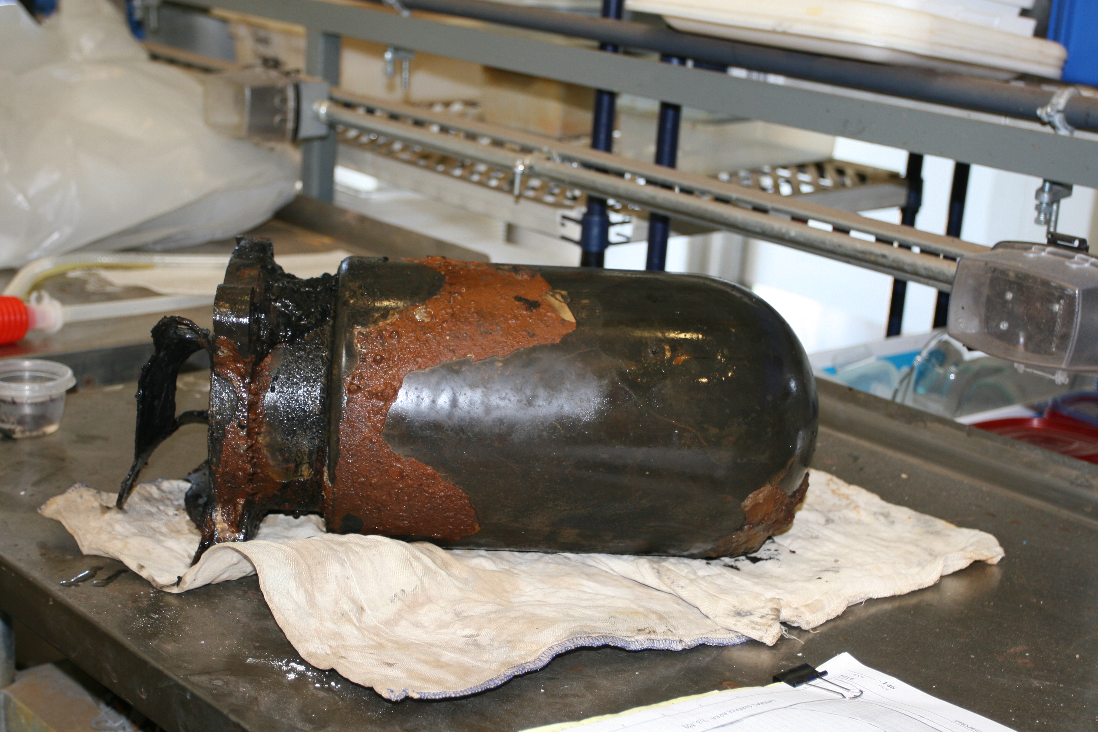
A detached air flask with its rubber gasket.
The final highlight of the week was the chance to use a Bruker Tracer III-SD X-Ray Fluorescence (XRF) device we had on temporary loan inside the condenser tank. The use of this machine gave us a chance to start determining the composition of the copper-alloy parts of the condenser.
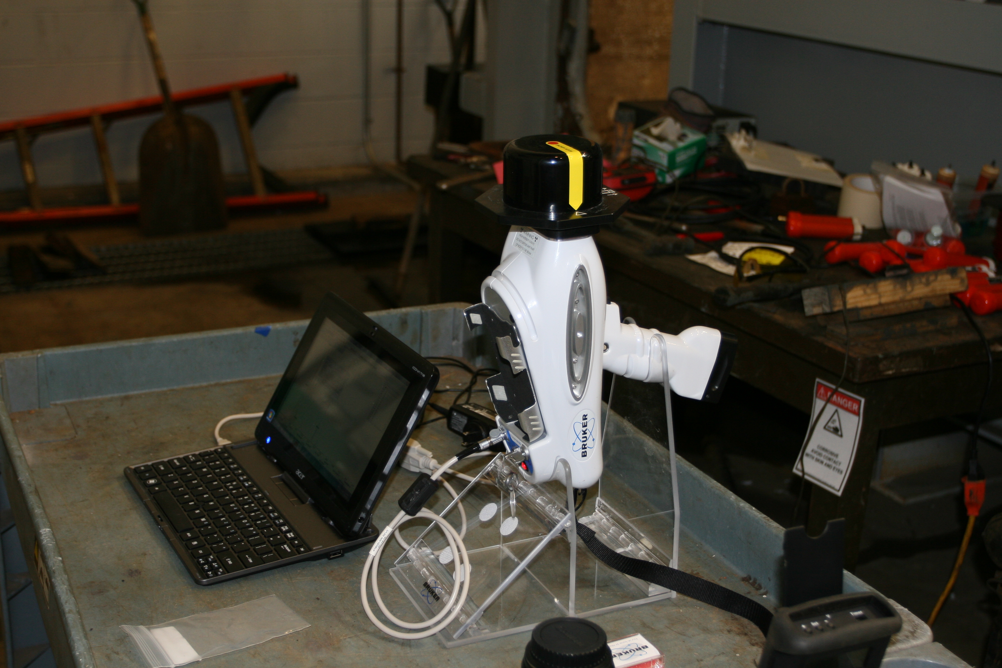
Calibrating the XRF before heading into the tank.
We will be in the condenser tank for the next couple of weeks. Check back to the blog for more updates or follow our progress via the web cams!