When the US Navy and NOAA archaeologists decided to recover the emblematic Monitor gun turret from the ocean floor, the entire engine room was in the way and therefore had to be recovered first. This included the main engine, ventilation engines, auxiliary pumps and the condenser. Now, in order to conserve these complex pieces of machinery, a large part of our job is to disassemble them. This allows for appropriate treatment of the different materials (iron, copper alloys and gaskets have different conservation requirements), while more exposed surfaces provide better extraction of harmful salts and thorough surface cleaning. Disassembly can be quite time consuming but there is no way around it! In 2019, one of the conservation team’s projects was to further disassemble the condenser (yes, parts had already been separated).
But first things first, what’s a condenser condensing and why?!
Condensers were invented in the late 18th century by a Scottish gentleman, James Watt, to make steam engines run more efficiently. Such engines used water properties to activate pistons. When steam (water in a gas form) located in a cylinder is quickly cooled and turned back to water (condensed), it takes up less space than in its gaseous form which creates a vacuum in the chamber. As a result, the piston is first pushed in one direction before being pulled back in the other direction when a vacuum is created by cooling down the steam. Originally, in order to create this vacuum, water was sprayed directly on the steam within the piston chamber. It worked well but overall wasted a great deal of energy by repeatedly cooling and heating the cylinder. James Watt therefore saw the need for an external piece of equipment, a “condenser”, where steam would be condensed away from the piston chamber. The addition of this device rendered steam engines faster, more efficient, more reliable and more economical… And consequently condensers were used in different configurations in all marine condensing engines through the mid-19th century.
What’s specific about Monitor’s condenser?
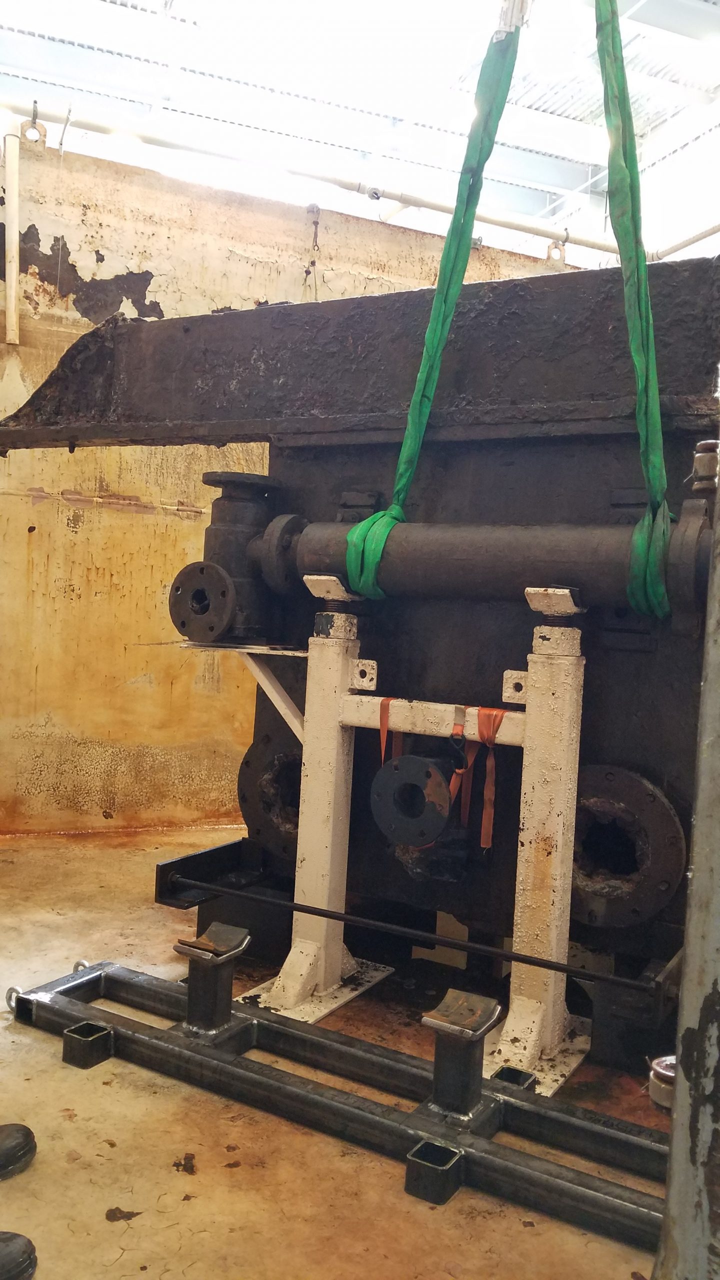
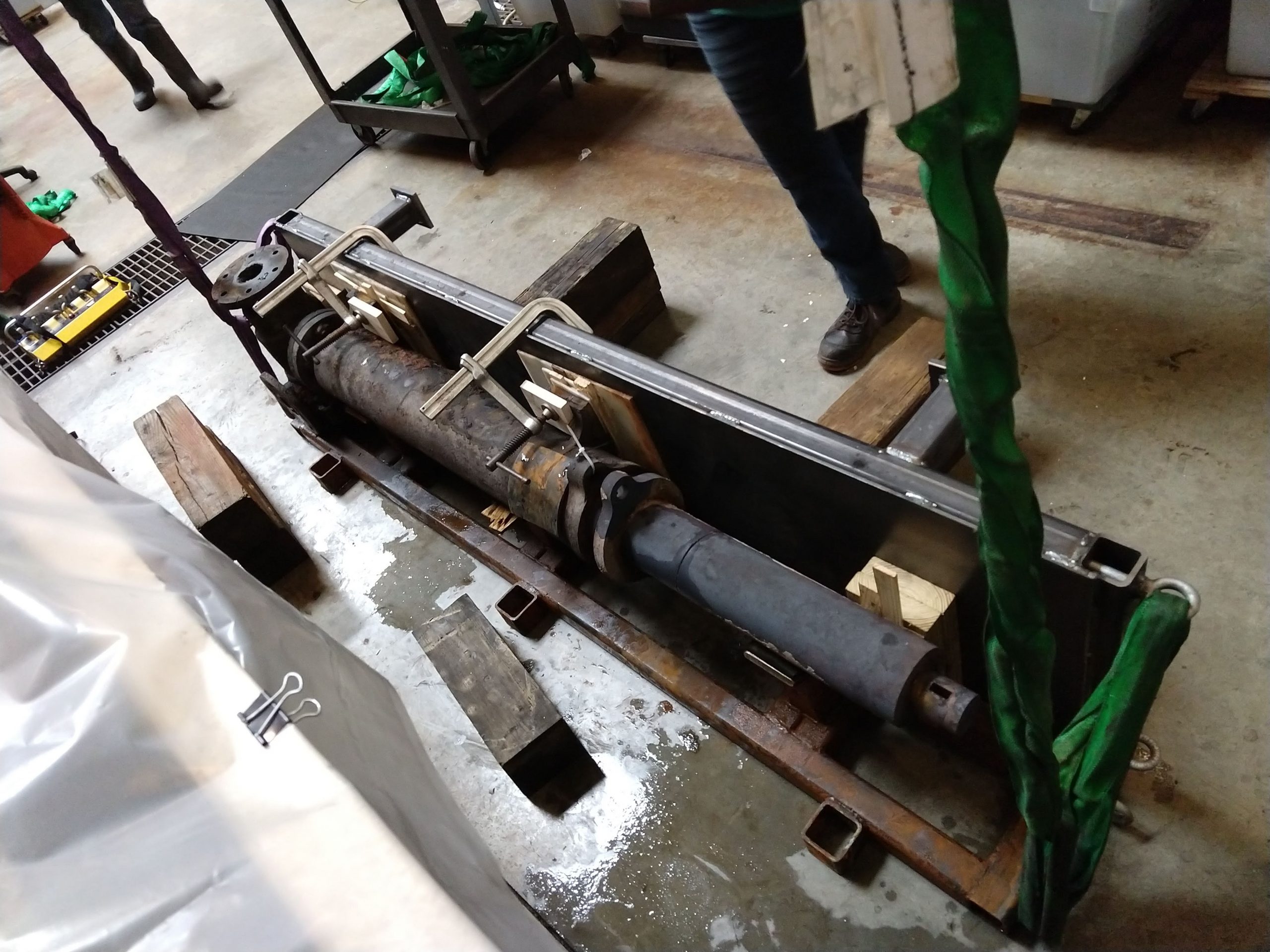
The condenser located on board Monitor is of the “common jet injection” or “contact” type (yes, there are multiple types!) Seawater is sprayed directly into incoming engine exhaust steam which is then condensed. The resulting mixture of condensate and seawater is then pumped by an air pump to the condenser hot wells where some is sent back to the ship’s boilers via a feed pump while excess is discharged overboard. The air pump and the hot wells are located in the condenser’s casing while the feed pump is attached to the exterior of the casing (Fig. 1; Hanley 2007). You still with me?!
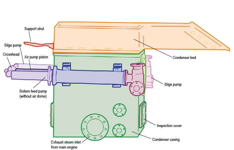
Figure 1 was made from a picture of the condenser taken in 2017. At this time, we had already removed the discharge pipe (a manifold type pipe, see this blog) and the air dome of the feed pump. This dome was there to dampen pressure fluctuations in the feed system and even flow into the boilers (see this blog for its removal).
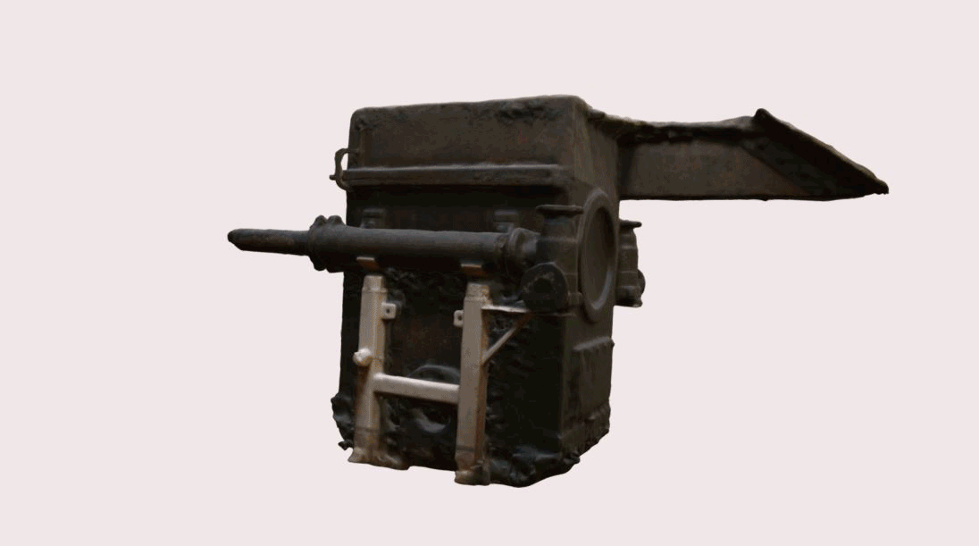
I’m going to get back to Figure 1 throughout the blog since the colors (make everything better… but mostly) make it easier to differentiate the condenser’s parts. Fig. 2 shows the condenser in 3D, still upside down in 2017, thanks to Hannah and her photogrammetric skills.
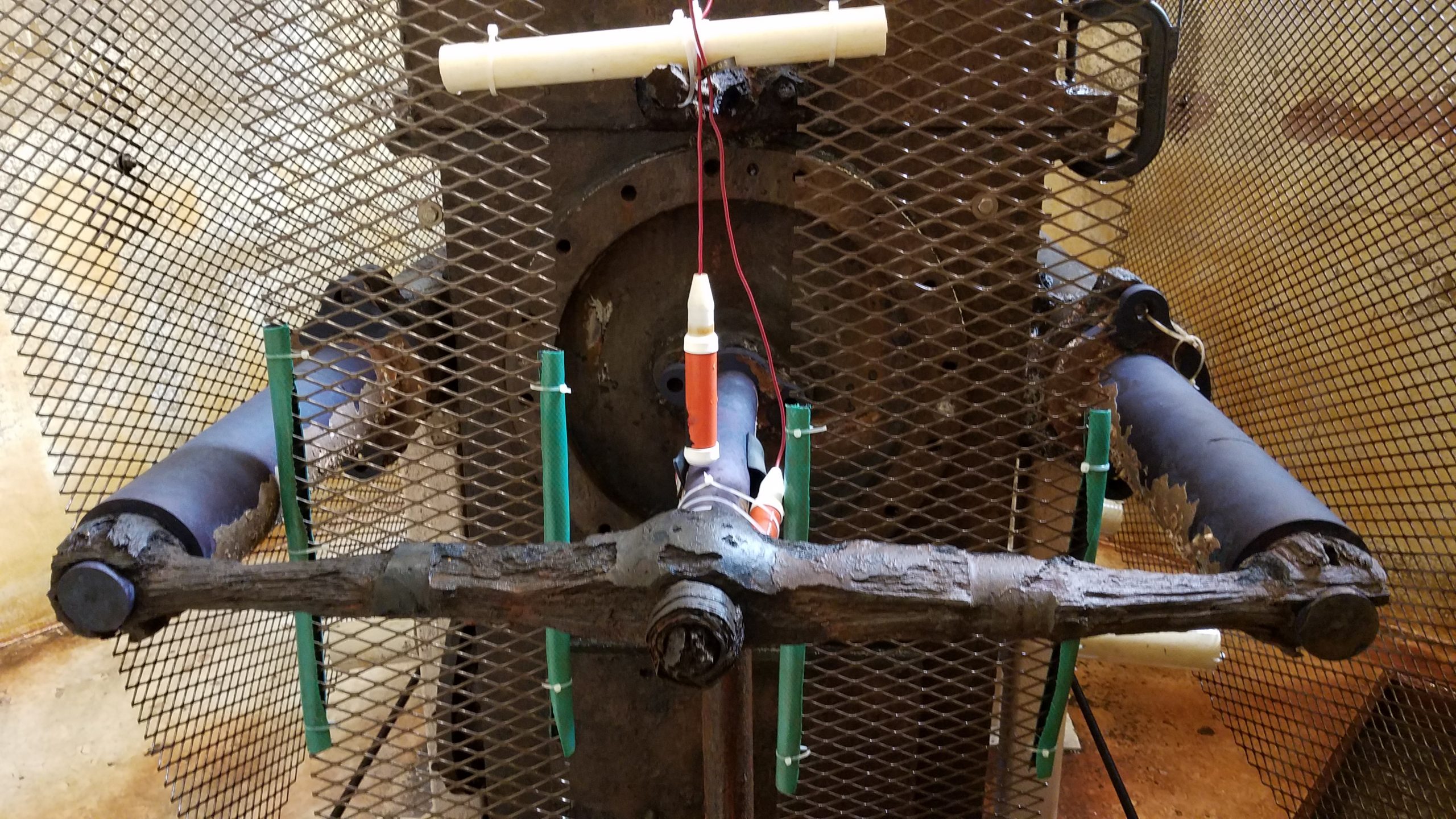
On Fig. 1 notice that there is a bilge pump attached to the opposite side of the casing from the feed pump. This is actually the ship’s main bilge pump and it has nothing to do with the condenser’s function! It is just sitting there for convenience. This disposition was apparently common at the time as it was out of the way and allowed to connect and power all three pumps (air, feed and bilge) to a crosshead driven by one of the engine’s rock shafts (Fig. 3). Pretty sleek!

“The injection-type condenser had a major drawback: the condensing seawater introduced atmospheric gases, SALTS and minerals. Evaporation in the boilers resulted in the buildup of sludge and encrustations which both damaged materials (e.g. corrosion) and diminished heat transfer efficiency. This necessitated frequent boiler blowdowns” (Hanley 2007).
Yeah… not ideal, salts and metals are nemesis, as we know it well in the lab!
So, what did we do to the condenser in 2019?
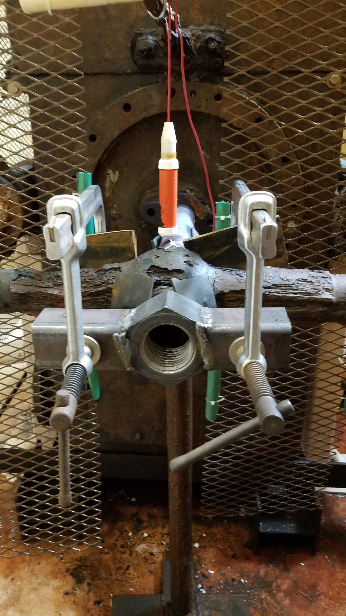
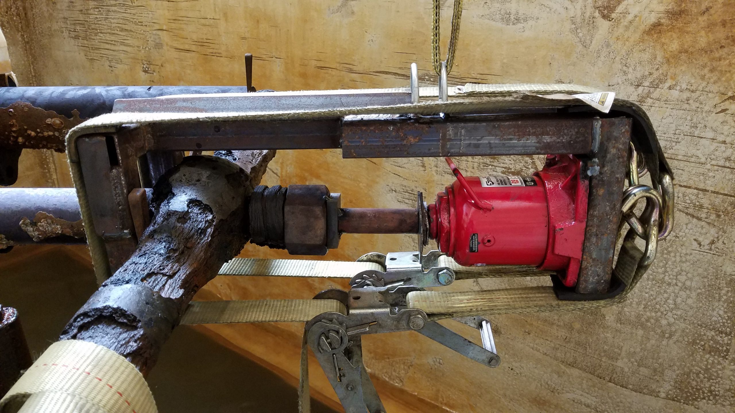
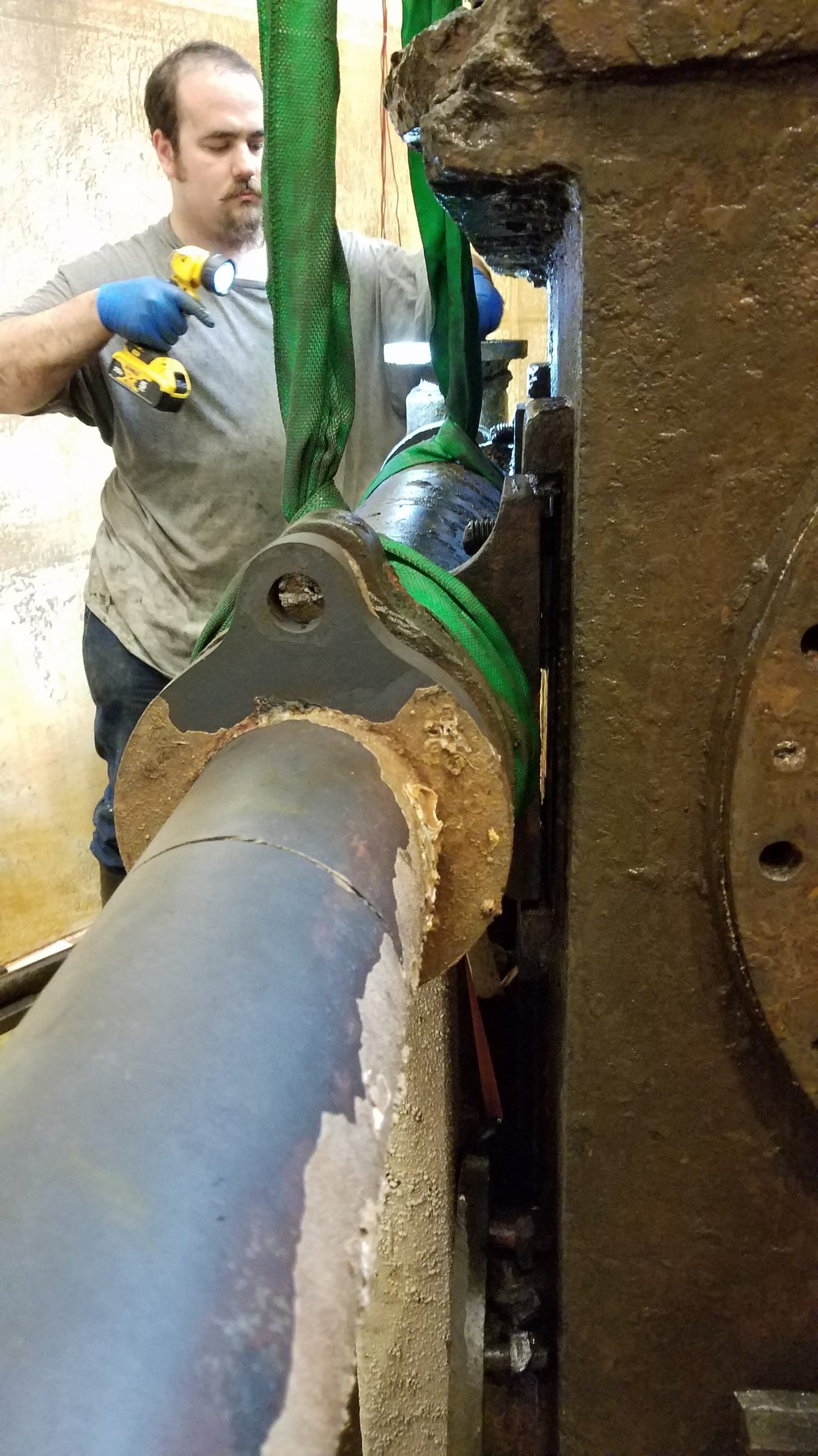
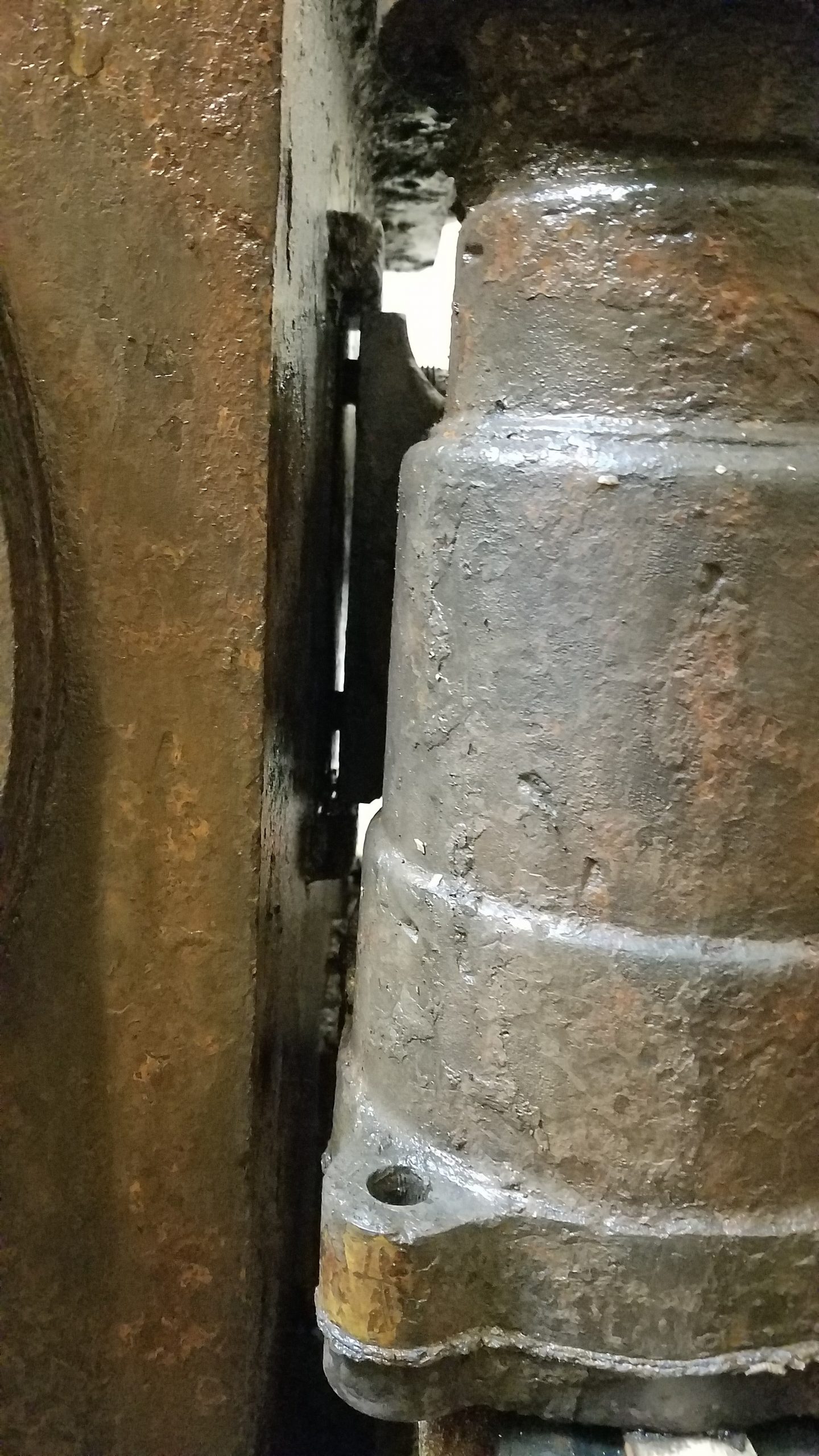
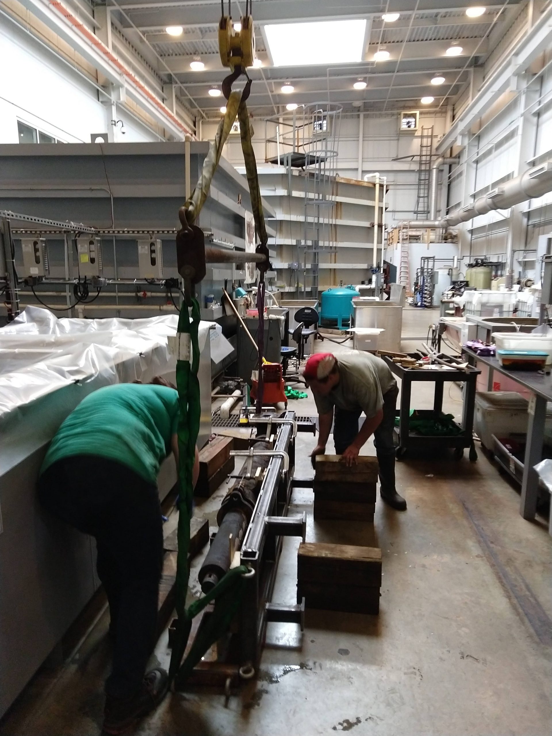
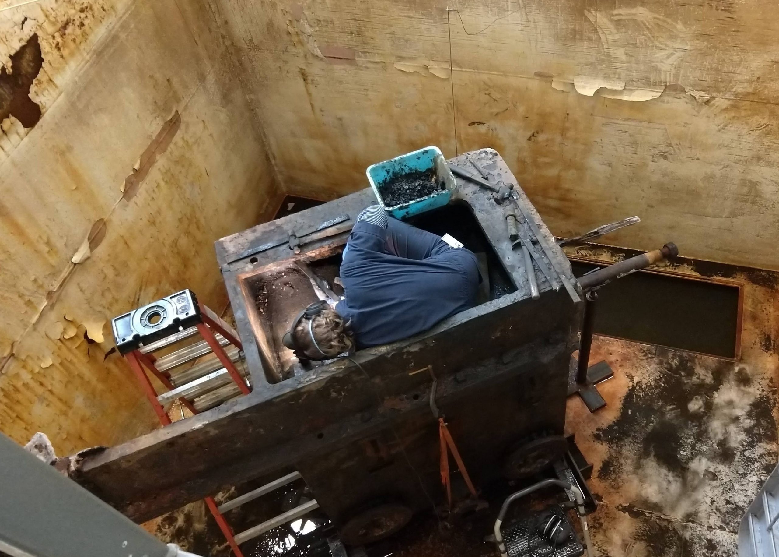
Considering that our ultimate goal is to get to the core of the problem… and eventually flip the condenser right side up and disassemble the mechanisms located inside the casing, both exterior pumps and the condenser bed (shown in orange in Fig. 1) need to be removed next. And the first step to take care of the pumps and bed was to remove the crosshead (Fig. 1 and 3). Sounds easy enough, right?!
Except it was not! The process took about a week, 4 iterations of a welded contraption and two 40-ton capacity jacks. The following gallery of pictures gives a peek at the process:
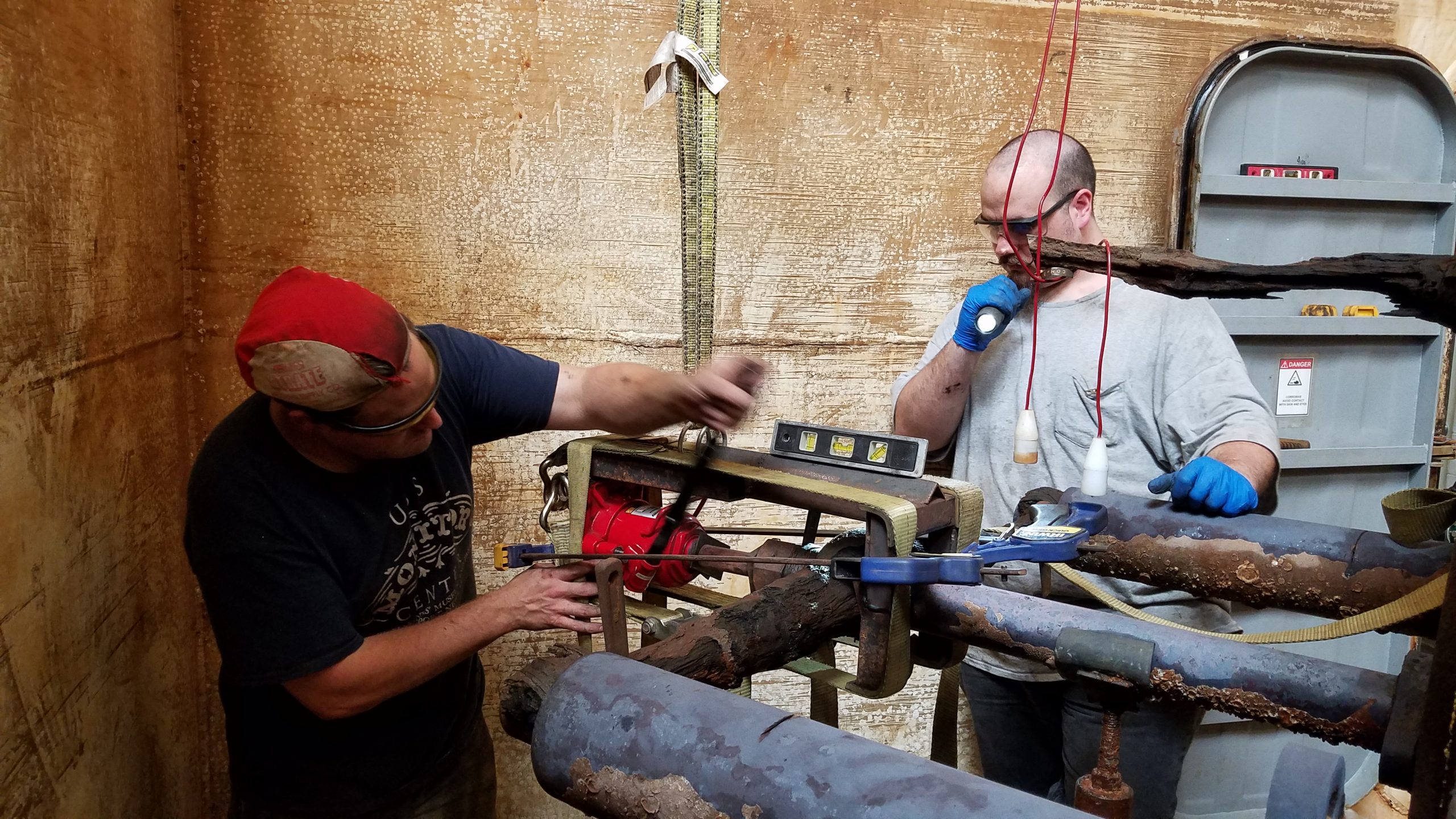
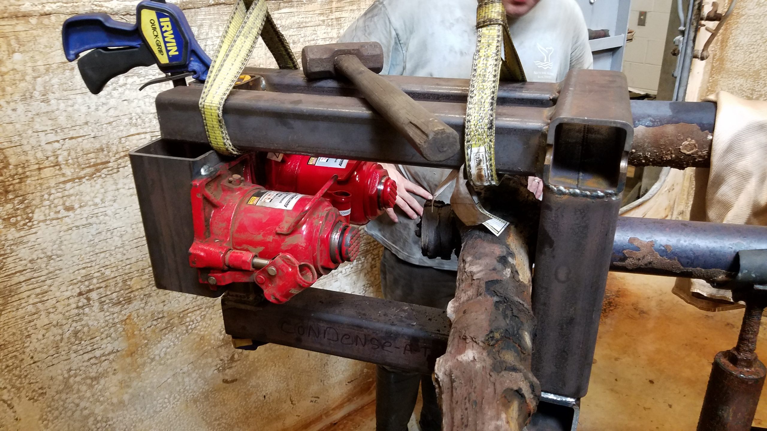
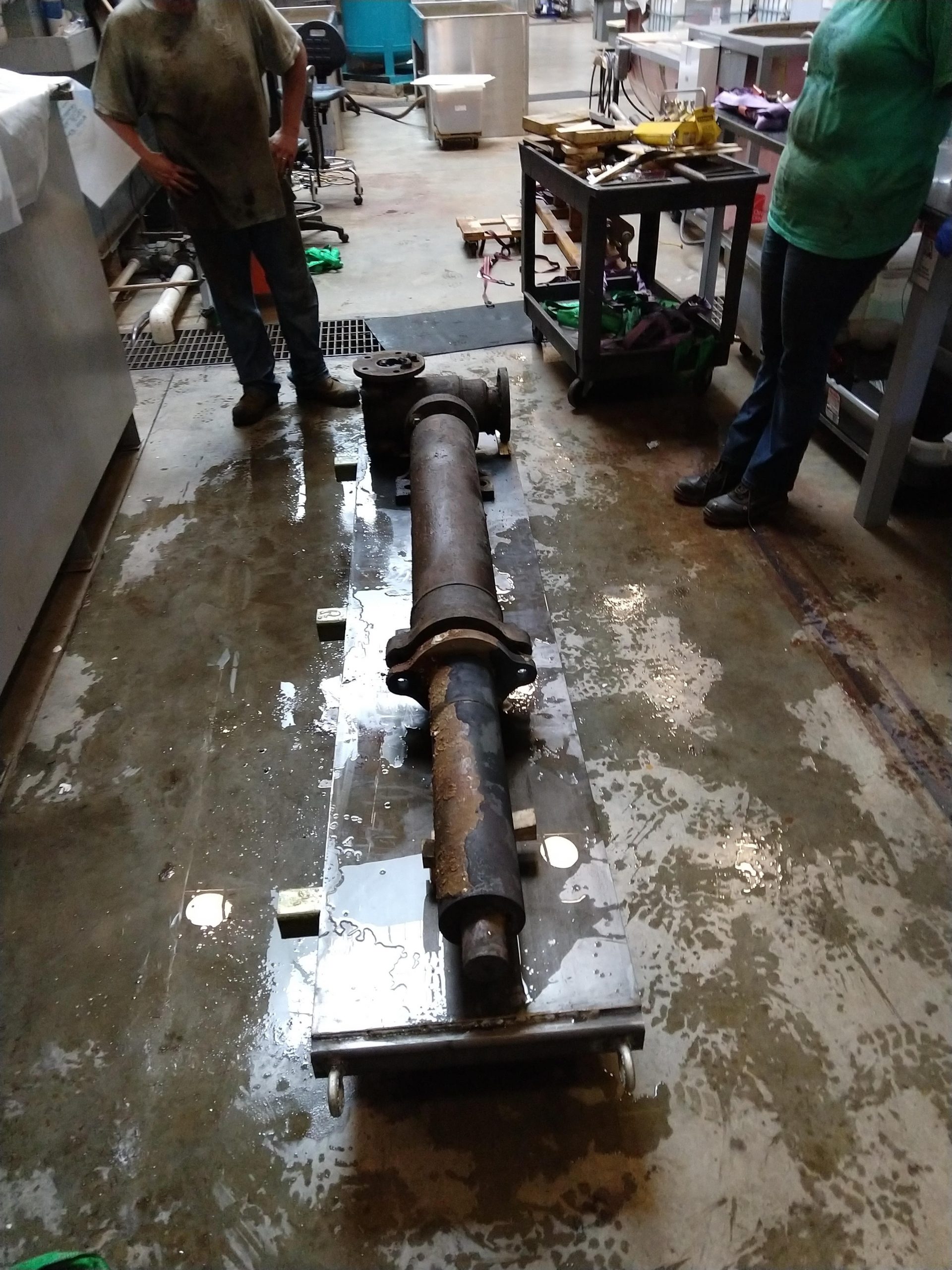
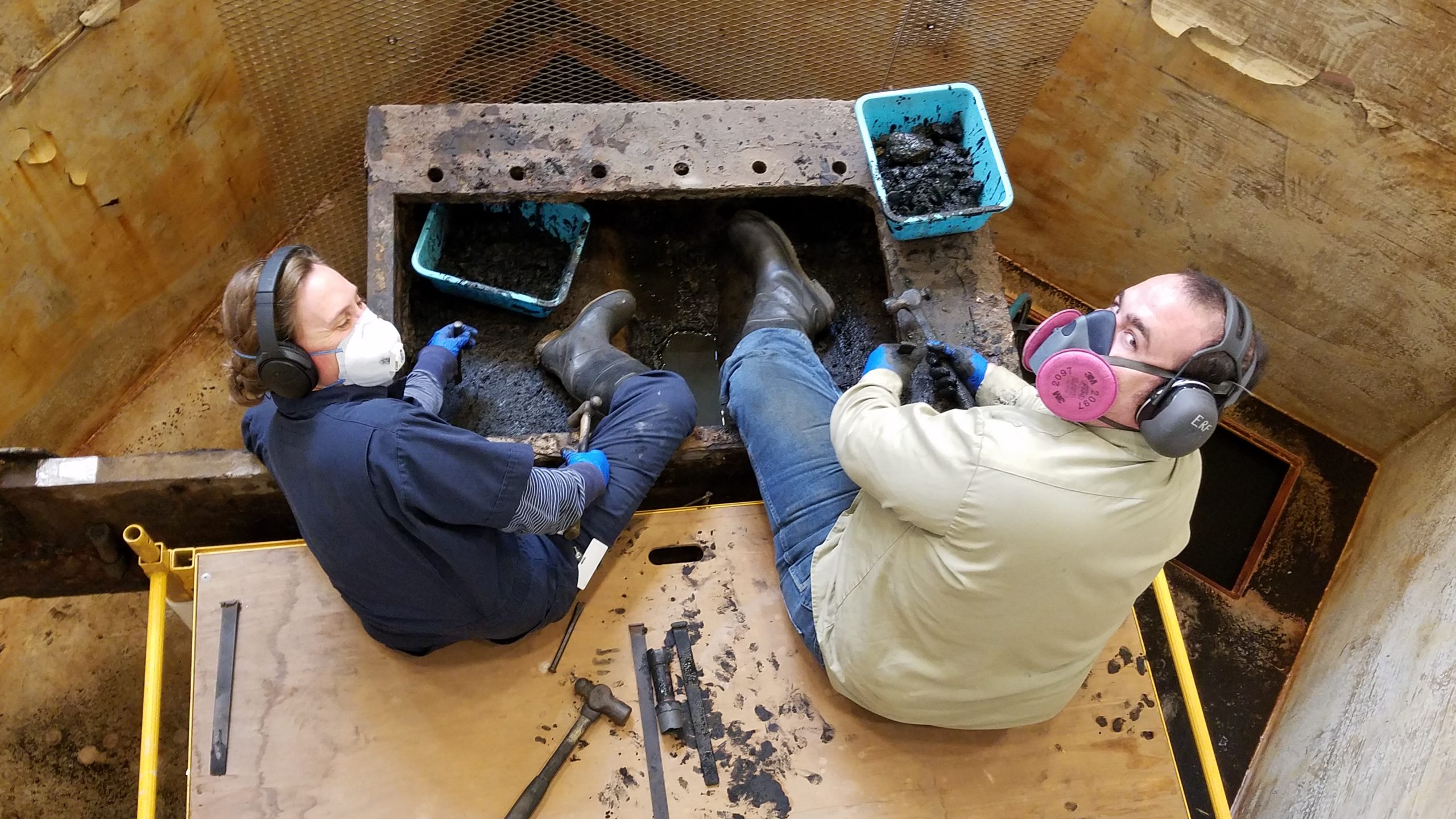
Following this success, we took a short break while Will was welding the next contraptions to safely remove the feed and water pumps from the side of the carriage. We had to remove them carefully and rotate them 90 degrees to assure physical stability. This meant that 3 supports had to be welded total: 1 to lift both pumps one after the other and 1 each for rotation and final support.
This process was surprisingly smooth but I guess, sometimes, good preparation pays off!
The next gallery provides an insight to the process:
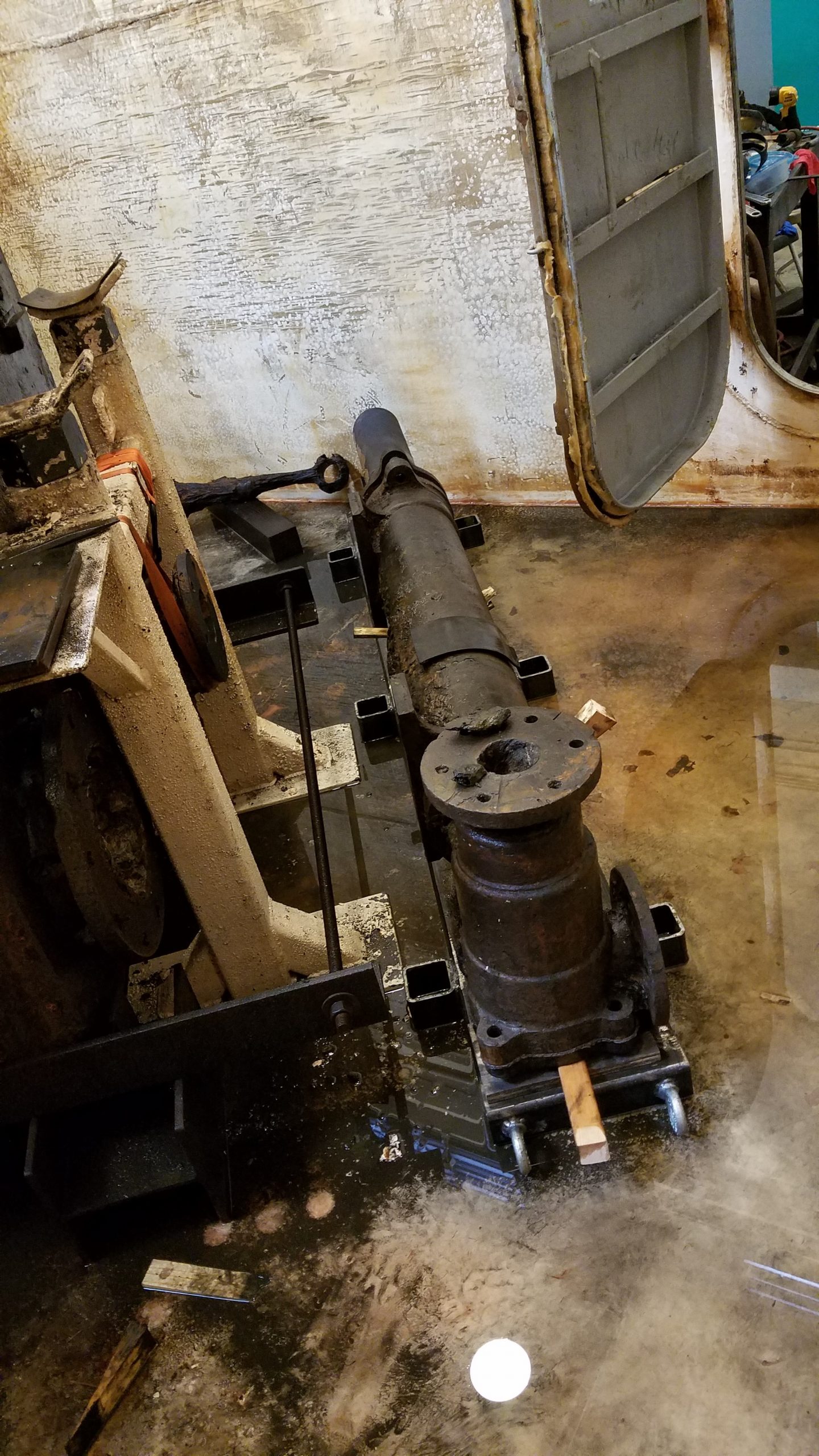
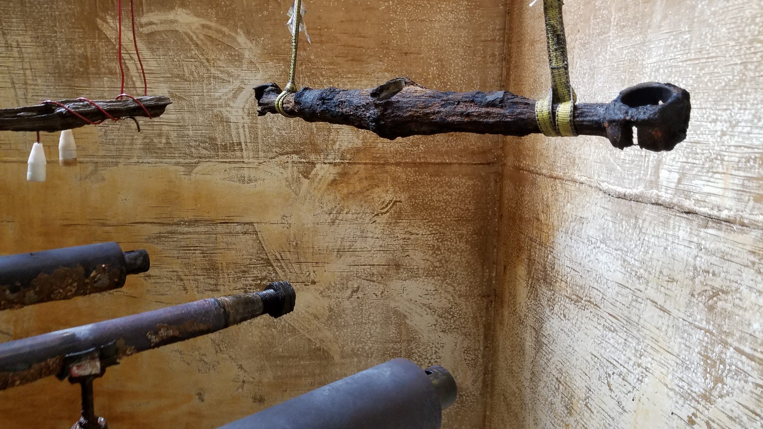
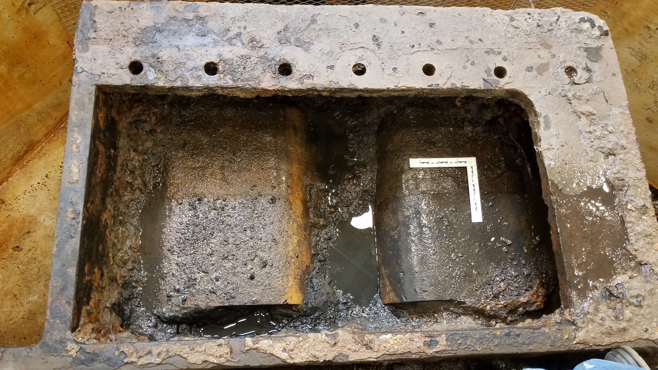
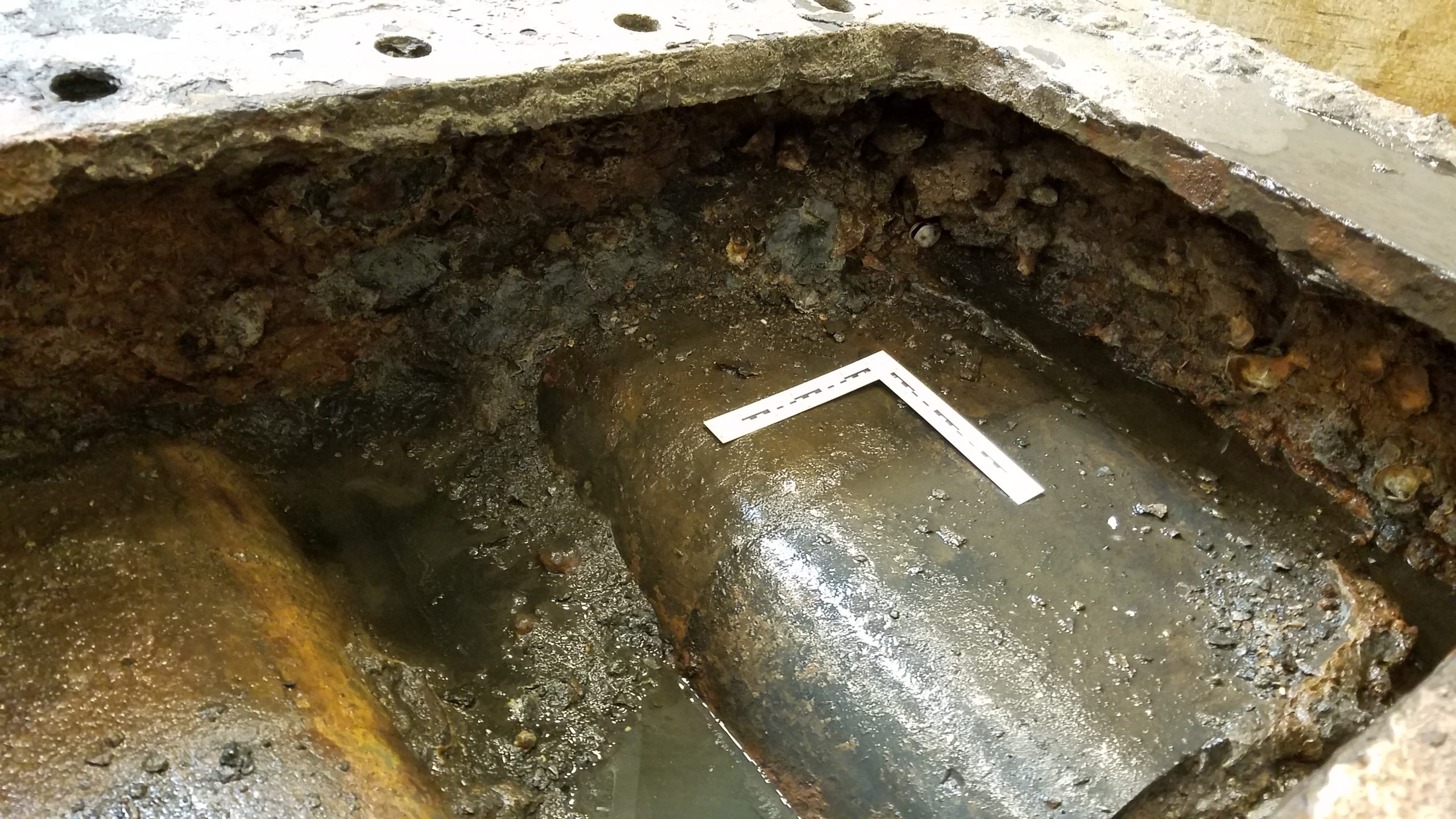
After setting up electrolysis for the pumps in another tank, we took a longer break to catch up on other projects and got back in the condenser in November 2019. Our mission then was to remove further concretions from the bottom (currently top) of the condenser in view of separating the bed section of the current assembly. Yet another contraption was designed by Will and we were going to need flat and clean surfaces to get a good and secure grip on the bed for the separation process.
The deconcretion proved tedious due to the limited working space. But we eventually managed (what is 3 weeks?!) and the condenser bed is now ready for removal! See the following pictures:
What’s next?
We were supposed to proceed to the bed separations after boring the Dahlgren guns this year so it was planned for March/April but you know the rest of that story…
So we are on hold with this particular project at the moment but look forward to achieving this major step which will finally allow us to flip the condenser right side up!! The condenser will then become the largest piece of USS Monitor to be standing in its original position!
Stay safe everyone!
References:
Hanley, Gerry. 2007. “Guidance Notes on the Design and Construction of the Condenser of USS Monitor. Internal report.” Conservation Department Internal Report, The Mariners’ Museum and Park.
For more information on the history of steam engines and condensers, check these references out:
https://babel.hathitrust.org/cgi/pt?id=wu.89071909386&view=1up&seq=11
Bourne, John. 1869. Recent Improvements in the steam-engine. London: Longmans, Green, and co.
Holmes, George C. V. 1897. The steam engine. London: Longmans, Green, and co.
Wallace, Robert. 1852. History of the steam engine, from the second century before the Christian era to the time of the great exhibition. London: John Cassel.